Modelling the P51 Mustang
a guest post by Tony LeGrand

The plan I used for this amazing RC warbird is about 1:6th scale, with a wing span of 1.6m, (65inches), and a fuselage length of 1.4m. A good .60 2-stroke, or if you hate the scream of a two’eee, .80 to .90 4-stroke like the Magnum .91 I will be using, will do just fine. A warbird should sound as close to the real thing as possible, so a 4 stroke is just the ticket in my opinion.
Materials List
Just how much balsa will you need to build this plane? In all the construction articles I’ve read, no one has said just how much material is needed to complete the project. So I’ll set a new standard for others to follow.
Balsa Sheet
(All sheets are 1.2m x 100mm) 12 sheets x 1.6mm for wing and tail surface covering; 5 sheets x 2.5mm for wing ribs; 4 sheets x 3.2mm for fuselage sides and formers; 1 sheet x 9.5mm for the fuselage bottom engine cowl and elevators; 1 sheet x 12mm for the radiator and engine cowl.
Ply Wood
500mm x 200mm of 1.5mm for fuselage doublers and wing servo covers; 200mm x 400mm of 3mm for wing brace, retract mount doubler ribs and fuselage formers; 300mm x 100mm of 6.5mm for engine mount former and retract mounting plates.
It is a good idea to kit up all your parts before the building frenzy takes place. If you have access to a photocopier use it to copy the parts from the plan and then use a clothes iron, (hopefully not the one your better half uses for the clothes), to transfer the image of the part onto the balsa or ply. I used a band saw to cut out the ply parts and the wing ribs in their corresponding left and right pairs. The rest was cut out using a hobby knife and a razor saw, take your time to make a good job of this, making sure that all cut outs are a snug fit for the stringers and spars that go into them. Finish off all edges with a sanding bar to level off any ups and downs, checking the fit of the part over the plan to make sure it is a perfect fit. You are now ready; let the building begin!
Use a nice flat building surface to make the plane on, I got hold of some cork faced display board, which is great for pinning parts onto as the glue sets.
Fuselage
The two 1.5mm ply doublers and spruce longerons need to be epoxied onto the 3.2mm balsa side pieces, making sure there is a left and right side and not two left or two right sides! Formers F1 and F2 are epoxied together with the tank side crutches, which fit into slots cut into each former. Make sure they are squared up before the glue sets. Mark the position of the formers on the inside of each sidepiece to make it easier to line them up over the plan. Once the parts have cured the sides and the rest of the formers can be fitted in place over the plan or set up in a building jig to keep everything lined up nice and square.
Because the fuselage sides need to be curved from just behind the wing, use some ammonia and water mixed 50/50 to wet out the balsa to allow it to follow the required curves of the rear formers. This part didn’t fit into the jig properly so I just lined up the centreline of the formers using pins placed in the top of each and then eyeing up through the pins to make sure they were all perfectly in line. I used rubber bands to hold the sides in contact with the formers until the glue and balsa dried. After the glue had dried, the front and rear top sections were cut to size and again wet out with ammonia and water to allow them to follow the tight curves of the formers. I used Saturn Hobbies Gator Bond to glue these pieces in position, as it allows you working time to position the parts in the correct spot. The cockpit bottom was then cut out and fitted into position. At this stage I decided to fit a retractable tail wheel, I used the medium sized Robart mechanical retract. A 3mm ply former was fitted from underneath to mount the unit securely into position. The bottom was then sheeted with 9.5mm balsa. The fuselage was then sanded to the required shape, getting rid of the ups and downs and other rough bits.
Cowl
 |
Almost finished fuselage with
sheeting in progress
|
Wing
I was very tempted to make up templates and go ahead and make up a foam wing, as this is my preferred method of building good straight wings. But as it didn’t have them drawn on the plan, a built up wing it had to be as it is my job to make sure the plan is correct in every detail and that all the parts fit together correctly.
 |
| All built up wing showing the flap and aileron servos. |
The wing is built in two halves over the plan by first pinning the spruce spars in position. The ribs from R2 outward were fitted to the spar, using a small square to make sure they were at 90 degrees to the building surface. (The centre rib R1 is fitted at a slight angle when the two halves are joined together to achieve the correct dihedral angle.) As the wing tapers towards each end in cord width and thickness, the rear of the ribs were packed to the correct height using a strip of balsa along the trailing edge. The plan shows two degrees washout built into the wing, and having had a few less than pleasant experiences with high and low speed stalls with a Spitfire and a Kittyhawk, two degrees of washout was a good idea.
The 9.5mm aileron rear spar was fitted to the rear of the ribs, checking that the washout was still set in the wing section. Next the 3mm false leading edge was glued into position, the 1.5mm shear webbing was then fitted to the rear edge of the main spare, by this stage the wing is starting to stiffen up nicely. The 3mm ply doublers for the retracts were epoxied into position before removing the wing half from the plan. With the wing upside down the rear 6.5mm drag spar was fitted as well as the 6.5mm ply retract mounting plate. With the two halves finished to this stage it was time to join them together using the ply dihedral brace. One half was weighted down on the board with the other end being set at 110mm above the building surface, giving 55mm dihedral under each tip. Slow set epoxy was used to give a strong bond and allow ample time to set it up without unwanted twists and other nasties.
 |
Wheel wells were custom made by
making moulds then vacuum forming the
sheet over the moulds.
|
A bell crank was fitted to one of the retract rods to allow it to move at right angles to the rod so that it activated the retractable tail wheel from the one servo. A quick release ball coupling allowed it to be connected up as the wing is put in position. The wing tips were made of block balsa sanded to shape and hollowed out to save some weight, before gluing them on the ends of the wing. The wing was fitted up to the fuselage and the underwing radiator section was made up and fitted into position using foam and fibreglass for the job instead of the suggested balsa on the plan, purely a personal touch as the build-up version is easily made if you don’t like the fibreglass idea. The wing then just needed a final sanding before covering.
 |
Finished retracts and air scoop.
Fixed undercarriage is optional.
|
The ailerons and flaps were then built up separately from the wing over the plan using ribs and sheeting with ply doublers fitted in the control horn mounting areas. Both wing control surfaces are hinged near the top edge, so each bottom edge was chamfered to allow the control to move up and down the required amount.
Tail Surfaces
These went together very easily, just like a very small wing really. The horizontal stabiliser was built up by first joining the tips, and leading and trailing edges together over the plan. I then packed it up so that the high point of the centre rib just touched the plan, then glued the rest of the ribs in position, working from the centre out to the tips. Once the glue has dried, remove it from the plan and sheet it with 1.5mm balsa. The vertical stabiliser and the rudder and elevators were built up in the same manner. Everything was then sanded smooth and the leading edges rounded off nicely, ready for fitting up to the fuselage.
The elevator control rod is fully enclosed in the fuselage so I had to manufacture a U piece which fitted into each elevator half with an arm in the middle to connect up to the control rod. This was made up using piano wire bent up with the arm bound with copper wire and then sweat soldered in position.
This was then fitted to the 8mm dowel control rod using a metal clevis and fitted into the fuselage from the rear. The horizontal and vertical stabilisers were then epoxied into position, making sure they were all square to the centre line of the fuselage. The control surfaces were then hinged using Dubro medium sized hinges, cutting the slots but not yet gluing them, this will be done just before it is painted.
 |
| Fin and Rudder are built up then sheeted |
 |
Elevators are solid balsa, the single
torque rod is about to be fixed in place.
|
 |
Rear of the fuselage with the elevator
torque rod about to be fitted to the elevator.
|
Balancing Act
It was time to put everything in position and see where the C of G was going to be. With the 91 MAGNUM four stroke up front I suspected a nose heavy plane and with the servo tray in the plan position this was very much so. Being a plumber in a past life I don’t like lead and won’t put it in a lovely aeroplane so things needed to be shifted around so that ballast was unnecessary. This was achieved by reducing the size of the full width wing mounting plate to allow the servos to be mounted as far back as possible but still allow easy access to them. The battery and receiver were also mounted under the servo tray, with this small change the balance point worked out spot on.
Covering
I have always wanted to try panel lines and rivets and all that stuff that makes them look like the real thing so this is how I did it. The whole ‘plane was sanded down with a final 320-grit paper before all the panel lines were marked in position with a soft pencil then each panel piece was cut out of a $2.00 roll of brown paper, leaving 5mm extra for overlap. Starting from the back and the bottom work towards the top and the front, glue each piece on using 50/50 PVA and water. The paper has a dull and shiny side so remember to put it on shiny side out as it gives a much better finish. Once it’s dried, coat the paper with the 50/50 mix on the outside, let it dry and then lightly sand with 600 wet and dry. Do this again and it’s ready for the rivets and removable covers to be put on.
Servos were mounted as far back as possible because of the larger engine up front, still plenty of room available.
The Mustang had flush rivets, so drops of PVA wouldn’t do for rivets. After a bit of thought I came up with the idea of using the end of a hypodermic needle ground flat. This was then pushed into the surface without braking through the paper and rotated to form a round dimple, the effect looked very authentic. The quick release fasteners were copied by using a piece of 1/8th brass tube used in the same way. The covers were cut out of light card and glued in position with PVA. A final light coat of PVA and water, another light sand and she’s ready for the painting.
 |
| Fully sheeted P-51 with custom cowl. |
Painting
I love the look of a silver Mustang but everyone paints them silver, so camouflage it had to be. Seeing Col and Judy Pay’s Mustang at Avalon air show this year and taking heaps of photos of it made it an easy choice as the colour scheme of the 3 Squadrons Mk IV Mustangs that served in the Italian campaign could be copied from them.
I had some sample pots of satin acrylic mixed up at the local hardware store at $6.00 per 250ml pot. The colours were chosen from the Dulux colour chart and matched the green and dark grey spot on. Some white toner was then just added to half a pot of the grey to lighten it up for the underside of the ‘plane. I used an airbrush to apply the paint only using 50ml of each colour. The acrylic dries very quickly and was easily fuel-proofed by giving it 2 coats of satin Estapol to keep the matt war-bird finish. Once it was dry, the decals that a sign writer friend made up for me on his computer were fitted in position. A final coat of estapol over these to seal the edges and to take the gloss off them completed the job.

Let’s Light the Wick
Having heard glowing reports on the latest CNC operated factories in China that are producing the Magnum range of engines, I contacted Chris White, the man behind Hobby Wholesale Traders, the importer of Magnum engines. After some discussion Chris recommended the XL91FS for the Mustang and also suggested I use one of the Magnum aluminium spinners for it as well.
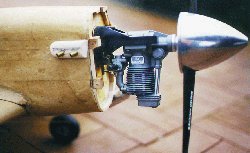 |
Magnum 91FS motor provided plenty of
|
grunt for this warbird.
A few days later a package arrived at my local hobby shop with the motor and spinner inside. The motor was bolted to the test bench and fuelled up with the recommended mix stated in the instructions. The main mixture needle valve was set at the recommended 2 to 2 1/2 turns, with the low speed one left as it came out of the box. The choke flap was closed against the venturi and the prop rotated 4 or 5 times. Releasing the choke, the glow-driver was attached and the 14 x 6 prop flicked backwards onto compression. The motor burst straight into life and sang like a bird! The running-in instructions were followed by running the motor at full throttle and controlling its speed by richening up the mixture then leaning it out for progressively longer intervals of time. This was done for 3 tank fulls, about 1/2 an hour total running time. This initial running showed that the engine was a very easy to start and a willing performer.The power plant was then put away while the Mustang was completed. This would be the real test for the Magnum, being fitted inverted in a very tight fitting cowl with minimal air flow. The motor was fitted to a nylon mount with a thrust plate fitted to give 2 degrees side and 1 degree of down thrust. To provide air flow the vent under the spinner was opened up and the cowl was cut out to allow the rocker cover to protrude through. Air could exit through the front four scale exhaust pipes on each side as well as the vented panels on each side and perforations drilled behind the glow plug access hole. A quick calculation had the correct 1 to 4 ratio of air going in and air coming out.
The motor was fitted up the night before the big day. I had just finished reading the latest Airborne and got an idea from Winchy’s ‘Engin-Ear’ article on oil recycling in Airborne issue number 182. As the motor is fitted upside down I would just run the breather pipe above the carburettor venturi and the oil will drip into it and end up out the exhaust pipe. Finishing the job at about 10pm, I filled the tank and primed it by holding my finger over the end of the exhaust pipe and turning the prop over 2 or 3 times, fitted the glow driver and, as I did on the test bench, flick it back onto compression. It again fired up instantly and settled down to a fast idle. A few rev ups and I stopped it so as not to upset the neighbours. A restless nights sleep was had, thinking about things that I might have forgotten to do before the test flight the next day. All was in readiness for the big test for both plane and motor.
Off into the Wide Blue Yonder
 |
Make dummy exhaust from scrap
balsa and brass tube.
|
The plane was pulled skyward in a surprisingly short distance for the size and weight of the airframe. It was then flown around at various throttle settings for about ten minutes and brought back to idle to do a stall test and a test for flap authority and both times, throttled back instantly to cruise away. My other 4 strokes hate being upside down and refuse to idle for more than a few seconds before cutting out. The Magnum fitted with an OS FS plug will happily sit there idling for a couple of minutes and still throttle up without any hesitation. The motor pulled the Mustang around the sky with great authority and even though it was still very tight and still set on the rich side pulled the plane vertically for a few hundred meters before stalling out. When it is fully loosened up it will go out of sight! Overall I must say that I am very impressed with this motor, it starts almost by merely looking at it and runs very smoothly indeed. For the bargain price of just under $400 from your favourite hobby ship, you will get a good reliable motor that I am sure will give years of happy flying.
The plan is very close to scale and lends itself to going all the way and doing a full detailing job. This is a fairly straightforward plan to build, and you could go down a different track and not fit the flaps or the retracts if you don’t want to. The wings could also just be covered with a film as well. All these mods would reduce the weight greatly and make for a very light wing loading. This would speed up the building time considerably and still give you a very nice looking and easy to fly war-bird. The flying characteristics are very forgiving, as it shows no sign of tip stalling on both take-off or landing. I’m looking forward to many missions with this great ‘plane.
No comments:
Post a Comment